SR6 Mods
TidyPrints SR6 mods
Wago 221 SR6 Power Bus
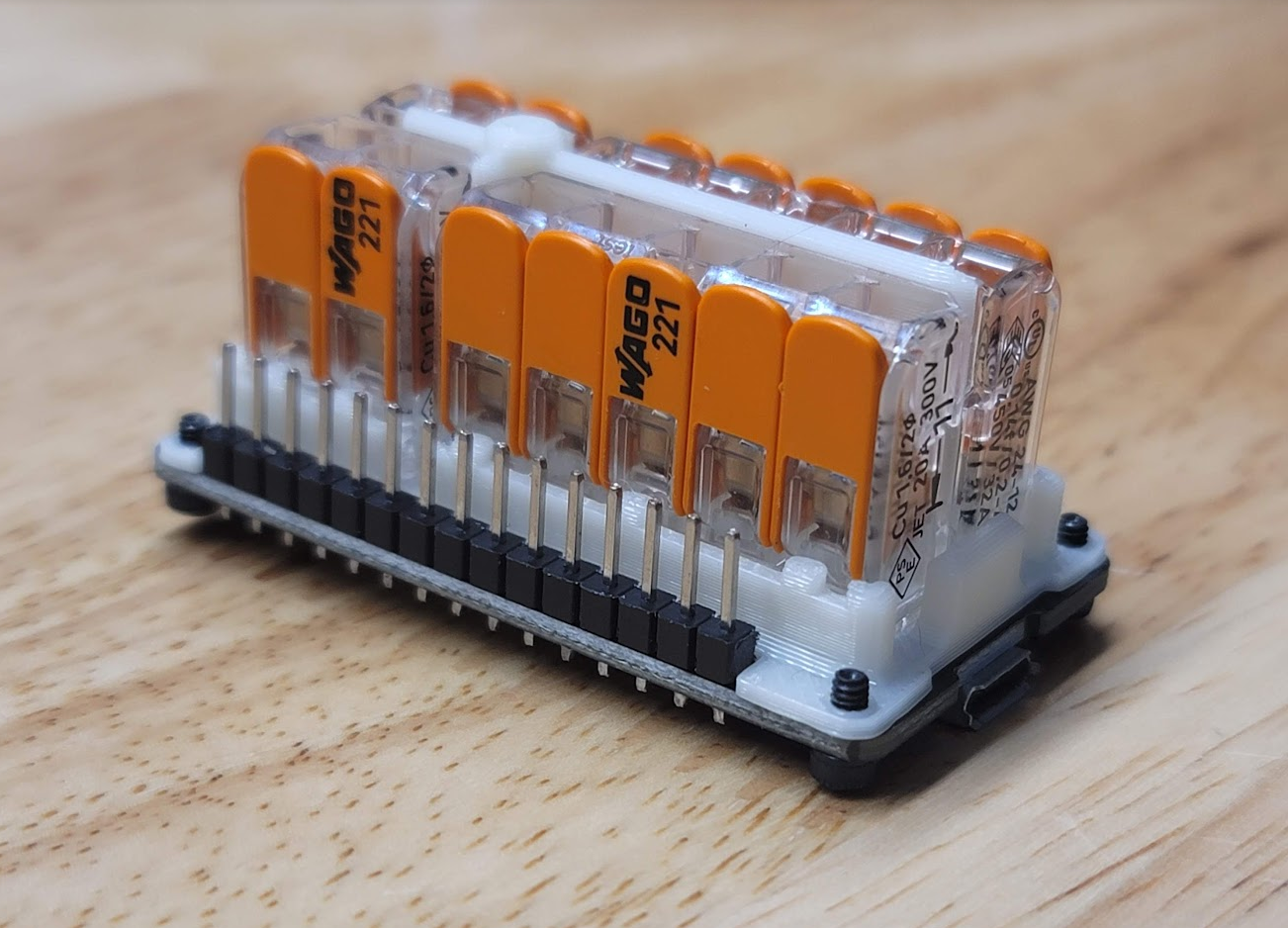
This sits on top of your ESP32 and distributes your robot's power without soldering. Strip 10mm of insulation off your servo power leads and tightly twist them together, positive with positive and negative with negative. Push the orange lever away from the clear housing, and insert them into the hole then snap the lever back in place. Give each lead a tug to make sure it's secure. I recommend not doing more than 2 wires per Wago hole. Bootlace Ferrules are a recommended upgrade to ensure proper electrical contact and can hold more wires reliably.
STLs:
https://www.patreon.com/posts/61550384 (free)
BOM:
Wago 221-415 x2
Wago 221-412 x2
Part Links:
https://www.amazon.com/dp/B07NKT2P2F/
Extra information:
SR6 Beta Jacked Frames
SR6 Beta Jacked Frames | Patreon
NOTE: If you are using JX servos, please get the JX versions below, they have slightly different mount patterns than most servos, which is enough to cause some alignment issues with M4 bolts. Thanks geogan for bringing this issue to my attention and helping to test fit the edited versions!
BOM:
- M4x14mm (x25) (Required)
- M4 Hex Nut (x1) (Required)
- M3x5x4 Heat Set Inserts (x4) (Optional, can replace with M3 Hex Nuts)
- 20mmx20mmx5mm or smaller adhesive heatsinks (x6, or more if you are using tiny ones.) (Optional)
These are the frames I am personally using and I really like them. They are drop in replacements for the stock Beta frames, however they do require the use of M4 hardware to attach the servos.
No nut or inserts needed, just screw them directly into the plastic.
Here's an aliexpress link to the M4 BHCS 14mm fasteners I used:
https://www.aliexpress.com/item/10000148429238.html?
The M3 heat set insert slots to retain the lid are optional, there are M3 hex nut slots that can also be used, but they must be inserted before the servo is fitted. (see above images)
I used M3x5mm(OD)x4mm(Depth) inserts, like these: https://www.aliexpress.com/item/1005002897983868.html?
I also added room for adhesive heatsinks on each servo. A small case fan (such as the tray fan I recently posted, or one added in a similar spot to the case) will push air around the servos, and they'll cool off even better with these cheap aluminum adhesive heatsinks. Any heatsink up to 20mm x 20mm x 6mm will fit, however I personally used 19mm x 19mm x 5mm because it's what I had available. Insert the servos first, partially screw them in, then peel and slide in the adhesive heat sink, pressing it firmly against the side of the servo. Fully tighten and align servos as usual. You will get a better result if you clean off your servo case gently with isopropyl alcohol, to remove factory grease.
Here's an amazon link to the heatsink assortment I got. You'll end up using these on other random electronics too, they're very useful: https://www.amazon.com/Easycargo-Development-Transistor-Southbridge-Northbridge/dp/B07KZG5433/
Finally, I added a little more clearance for servo wires. I use ds3235sg servos which happen to be quite short, and stock frames were pinching my wires more than I liked. There's also zip tie holes if you'd like to retain your cables a bit.
Both frames are attached in one STL, no supports needed, I recommend 4 perimeters (approximately 2mm thick walls for most people's print setup) and 40% infill for these parts (gyroid preferred, not very important).
There are two small tabs that are break off supports for the servo wire clearance, check above image.
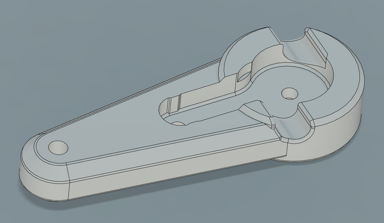
SR6 Beta1 Horny Pitch Arms
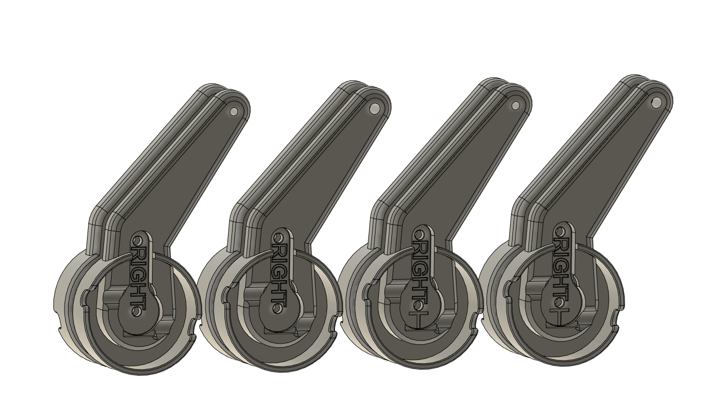
NOTE: I've updated this pack to contain both stock thickness arms and arms that are reduced by 0.5mm (some servo splines are a little farther out and this can cause the pitch arms to rub together more than desired) as well as arms that have 3mm and 4mm holes, if you find yourself using 3mm ID rod ends.
These are the same as the stock pitch arms except for horn screw access and (on some) a 0.5mm reduction on the "bottom" where the two arms are touching.
STLs:
https://www.patreon.com/posts/sr6-beta1-horny-58146242 (free)
BOM:
None (plastic only)
SR6 Beta1 Horny Arms
These are almost identical to the stock SR6 Beta 1 arms with the following differences:
Servo horn screw access
Slightly tighter tolerances (0.2mm on each side) at the end of the horn, for less wobble.
STLs:
https://www.patreon.com/posts/sr6-beta1-arms-58451637 (free)
BOM:
None (plastic only)
SR6 Fan Mount
Made this mount in the process of a more ambitious mod, but it's been working well for me so I decided to put this version out. The ambitious version is planned to have a 3S BMS built in, but I likely will use these same clamps as they've been great so far. These clamps can open up to 45mm (1.75 inch) and the mount angle is 25 degrees.
The stock SR6 base doesn't have a hole for this fan, so I've included a cut guide that you can use to trace the proper size hole. The SR6 base plastic is 3mm thick at that point, and can be drilled out or cut with a dremel/jigsaw. There's other ways to mount fans but I wanted to avoid possible lid collisions by moving it away from the unit's front.
BOM:
- 2x VIVO Aluminum C-Clamp "MOUNT-CP02" (20 usd for a 2 pack https://www.amazon.com/gp/product/B09WJMCDCZ/)
- 8x 1/4-20 x 1/2 inch or 5/8 inch length, either length works. (9 USD example assortment https://www.amazon.com/dp/B07C9MWCSP)
- 4x M4 x 20mm (Part of SR6 BOM, for mounting)
- Optional
- 40mmx10mm 5v fan
- 4x M3 x 12mm or 14mm (for the fan)
SR6 Limiter Arms
These arms add a little tab on each side that prevents the arm from going more than a few degrees beyond it's range. During normal use these tabs should never collide, however they should 1: mitigate twisting after an esp32 brownout and 2: make handling the SR6 much nicer.
Image 1 is how my SR6 naturally sits after installing these arms, and image 2 is what it looks like when lifted by the receiver. This also means that the startup homing is less sudden, since the arms can't move far out of their normal range due to gravity.
These arms also have slots for tightening the M2 servo horn screws.
BOM: only plastic
Note: when installing these, you can leave the metal servo horns connected and just undo the screws, which means there's no need to adjust your zero points.
SR6 Beta Fan Tray
This uses a small 4010 fan to blow air (mostly) out of the servo gaps, via an air intake. You can stuff a little crumpled up scrap of paper in the gaps of the micro usb port then fully tighten down the ESP32 if you want to direct even more air out of the servo gaps. Be sure to not compress the buttons.
You must have at least 37mm between your servos. This is 1mm more than Tempest's tray design. The 40mm fan is lower than the servos but very long servos may not fit with this tray. If it's close, you could add a washer between each servo and it's frame to get you about 0.5mm per side extra, which should be the same as the stock tray.
You can mount a power plug via zip tie like the stock tray, or mount one with a 13mm hex nut that it screws into. There are two holes for switches that you can punch out with a screwdriver, and two holes for a future power bus mount.
Print at 0.2mm layer height and be sure that you have the settings that allow bridging turned on in your slicer (this varies slicer to slicer). Avoid extrusion widths larger than 0.45mm on this model.
BOM:
4010 5v Radial Fan with 36mmx36mm mount holes, such as https://www.amazon.com/gp/product/B07RMY75GH/
- 4 - M2x6mm
- 2 - M2x10mm
- 1 - M2x20mm
- 1 - M2 Hex Nut
The M2x20mm is optional but nicer to clamp the assembly together if you've got it, but can be replaced by a screw 6-10mm on each side. See images for screw locations. You can power this fan directly off the ESP32 by plugging the JST into VIN and GND. Optionally you can add an adhesive heatsink to the esp32, but I do not think this is needed at all with the airflow so close to the heat spreader of the chip.